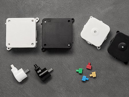

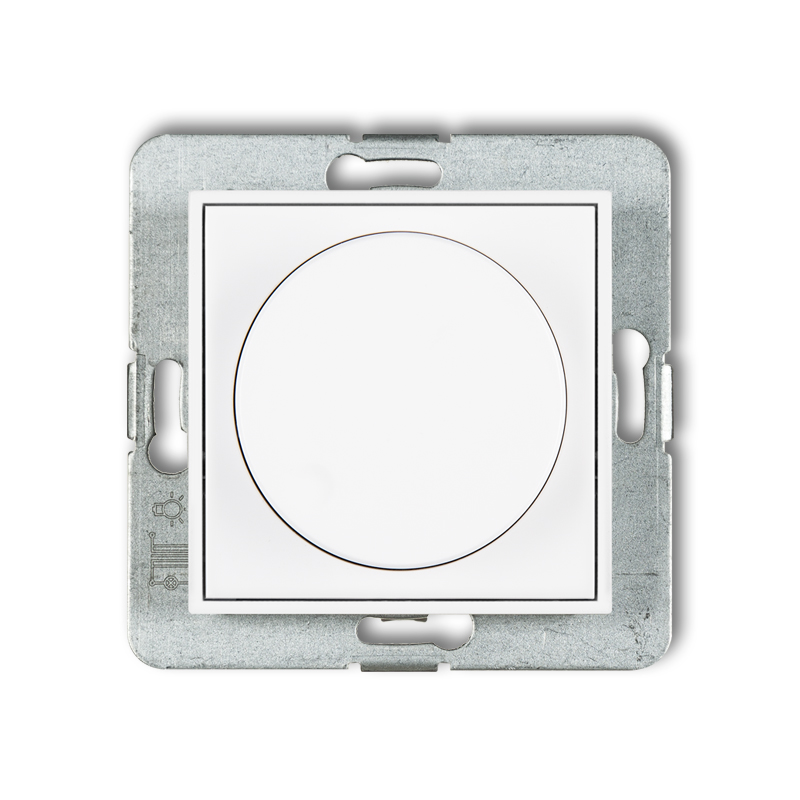
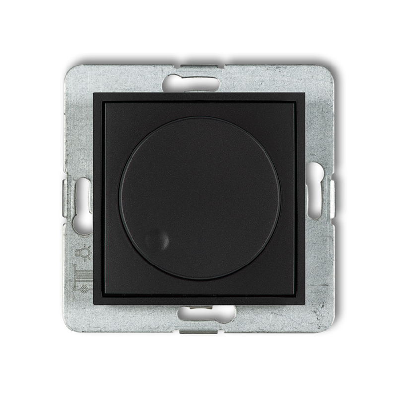
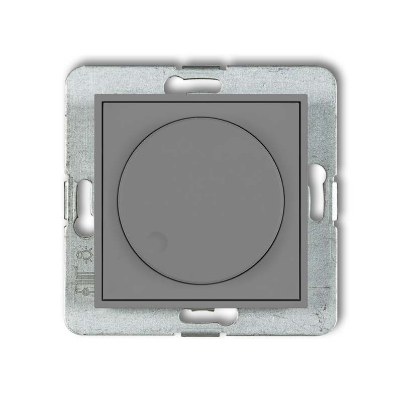
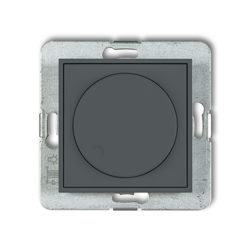
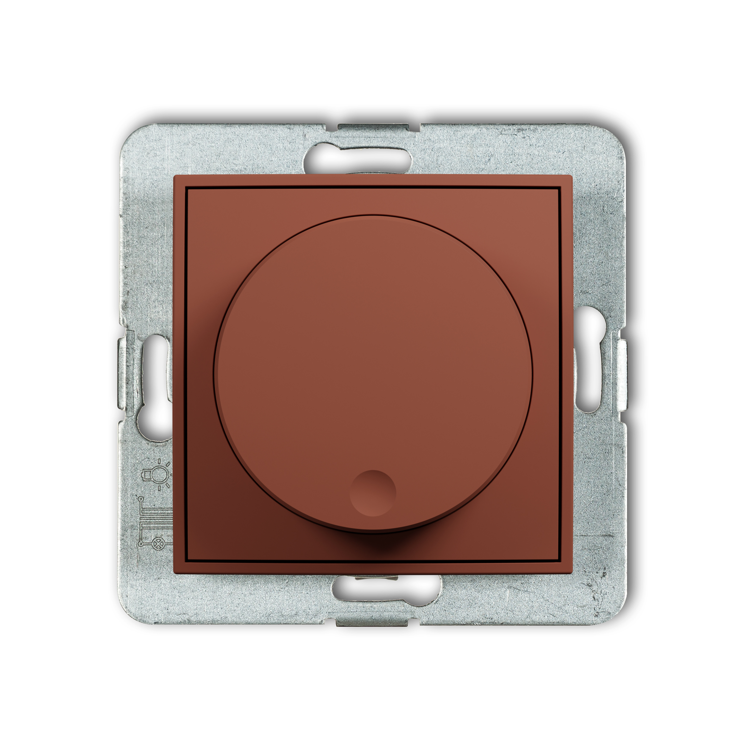
Electronic dimmer push-rotary mechanism for use with 1-10V voltage-controlled power supply unit
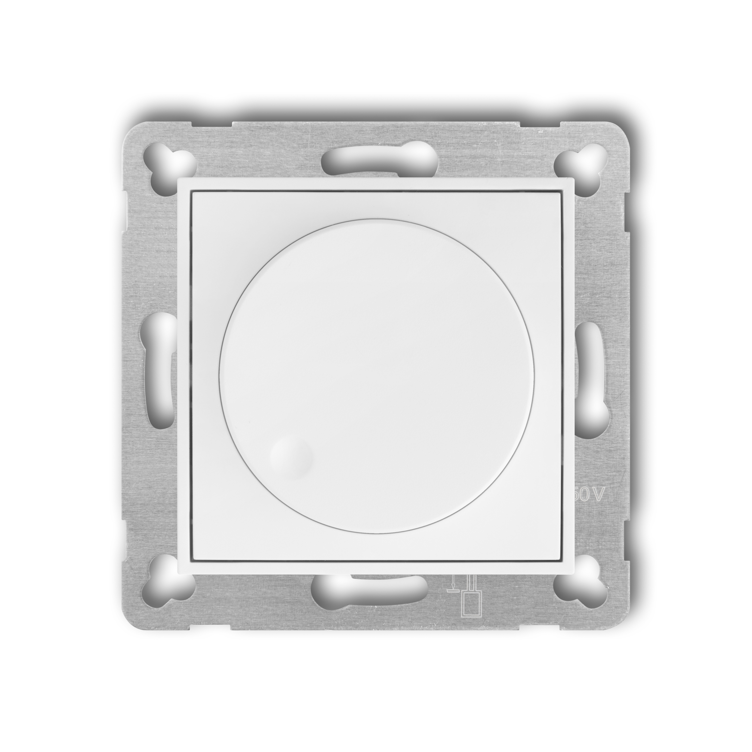
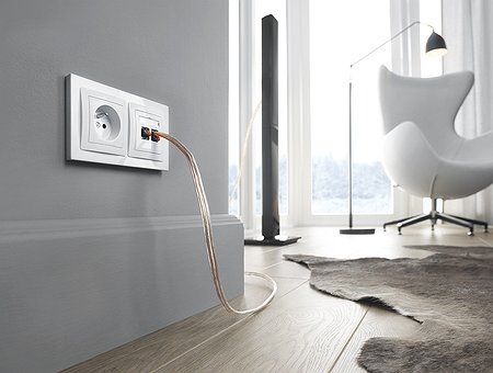
white
IRO-3
-
white
IRO-3
-
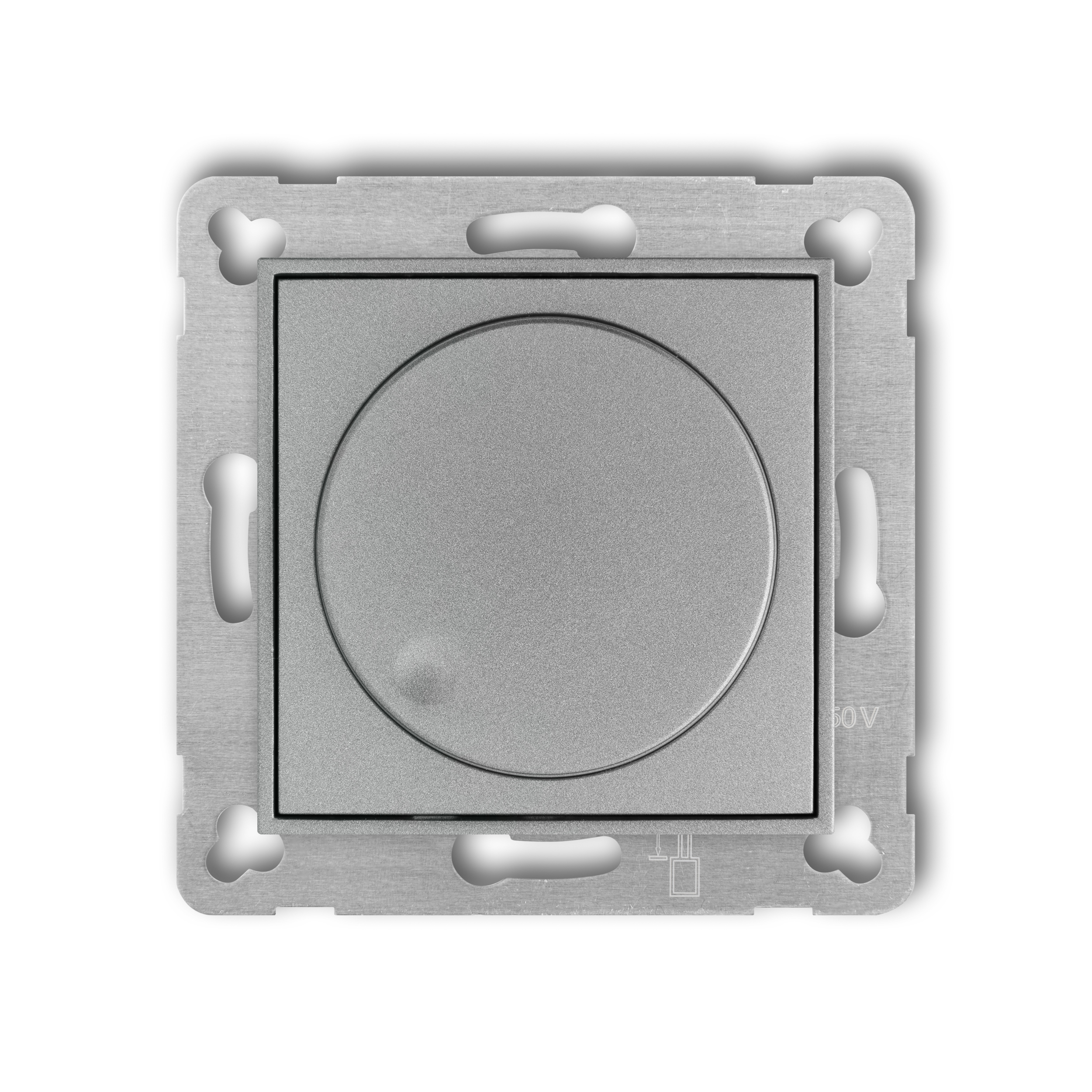
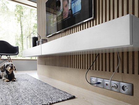
silver metallic
7IRO-3
-
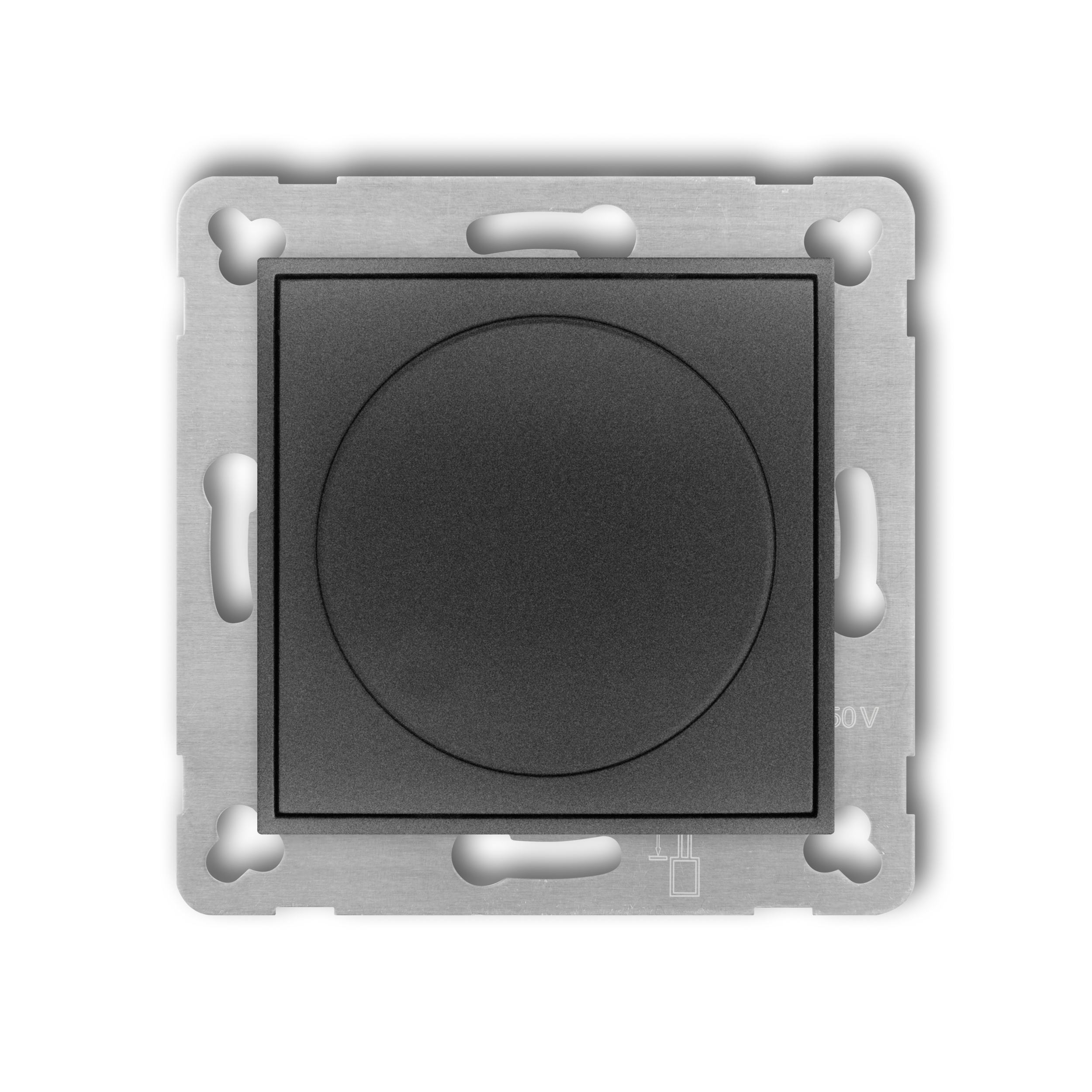
graphite
11IRO-3
-
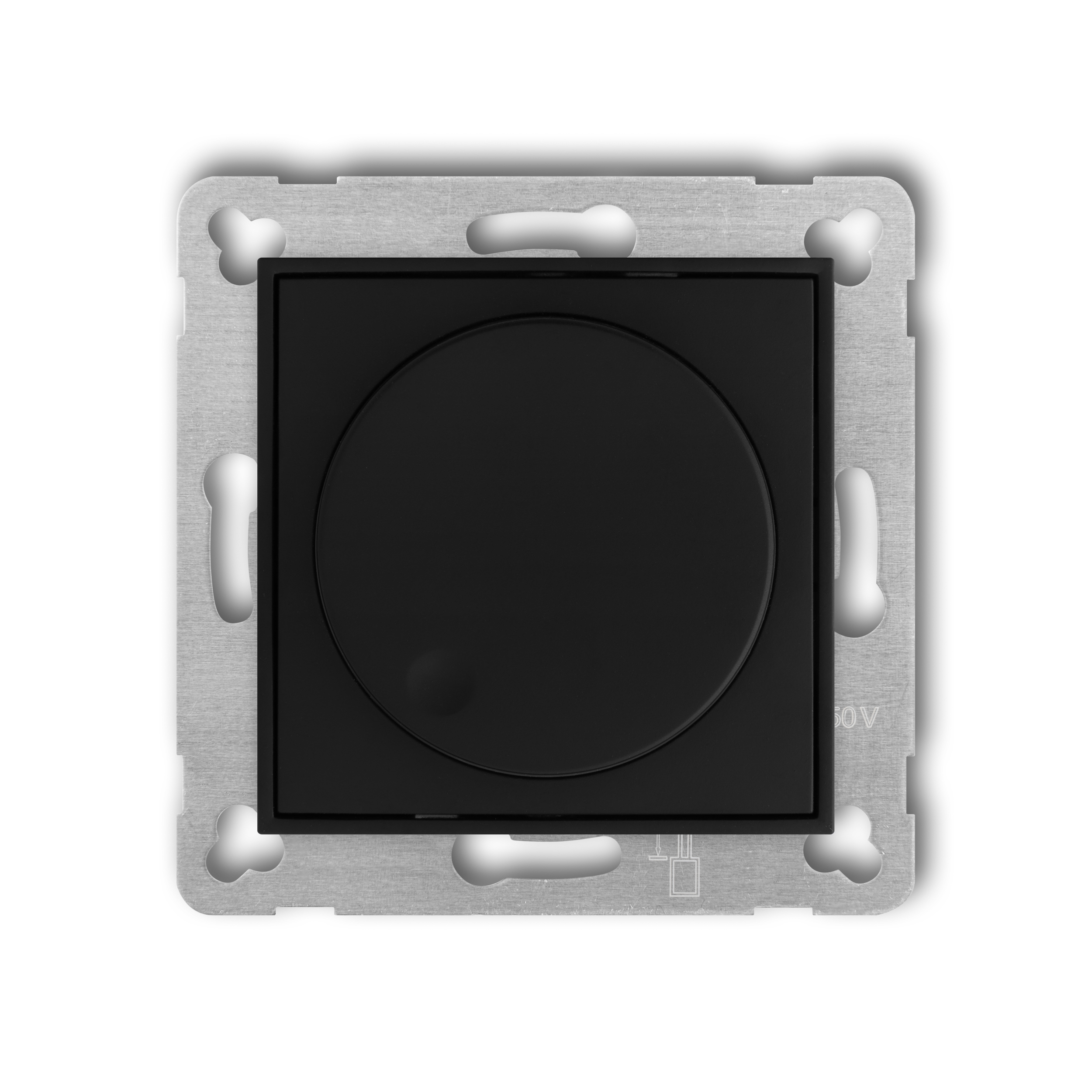
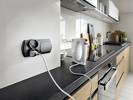
matt black
12IRO-3
-

matt white
25IRO-3
-
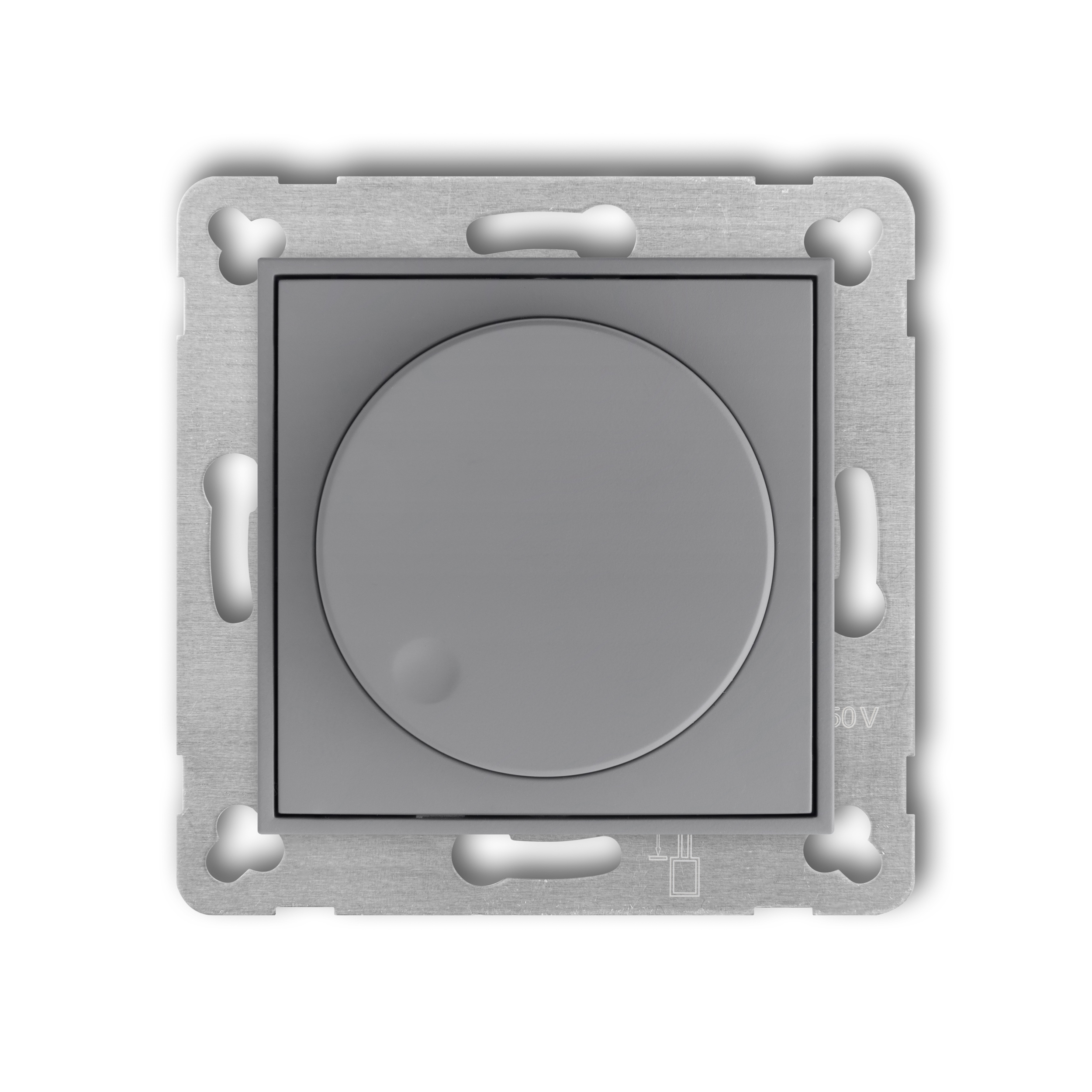
matt grey
27IRO-3
-
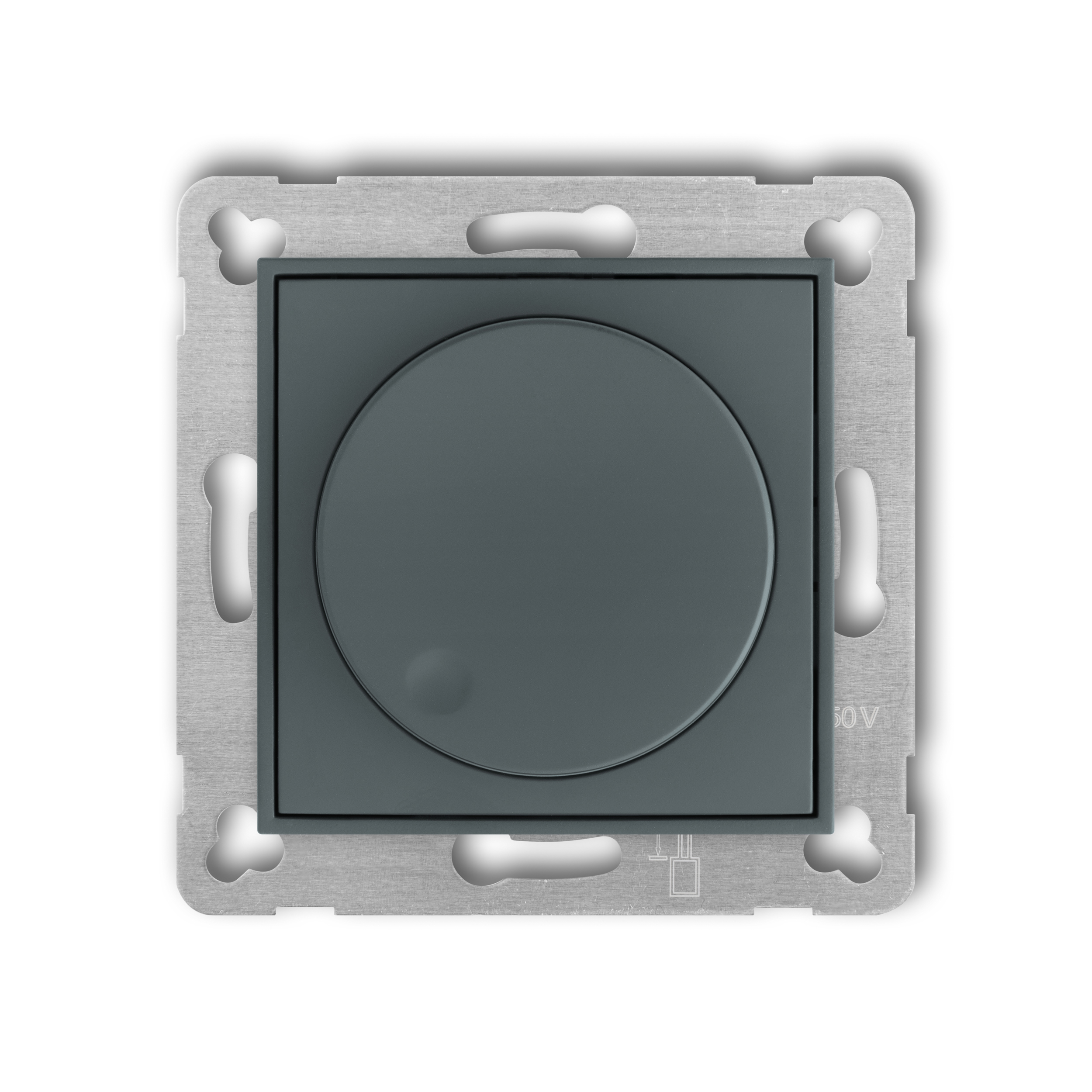
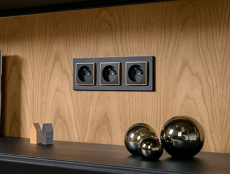
matt graphite
28IRO-3
-
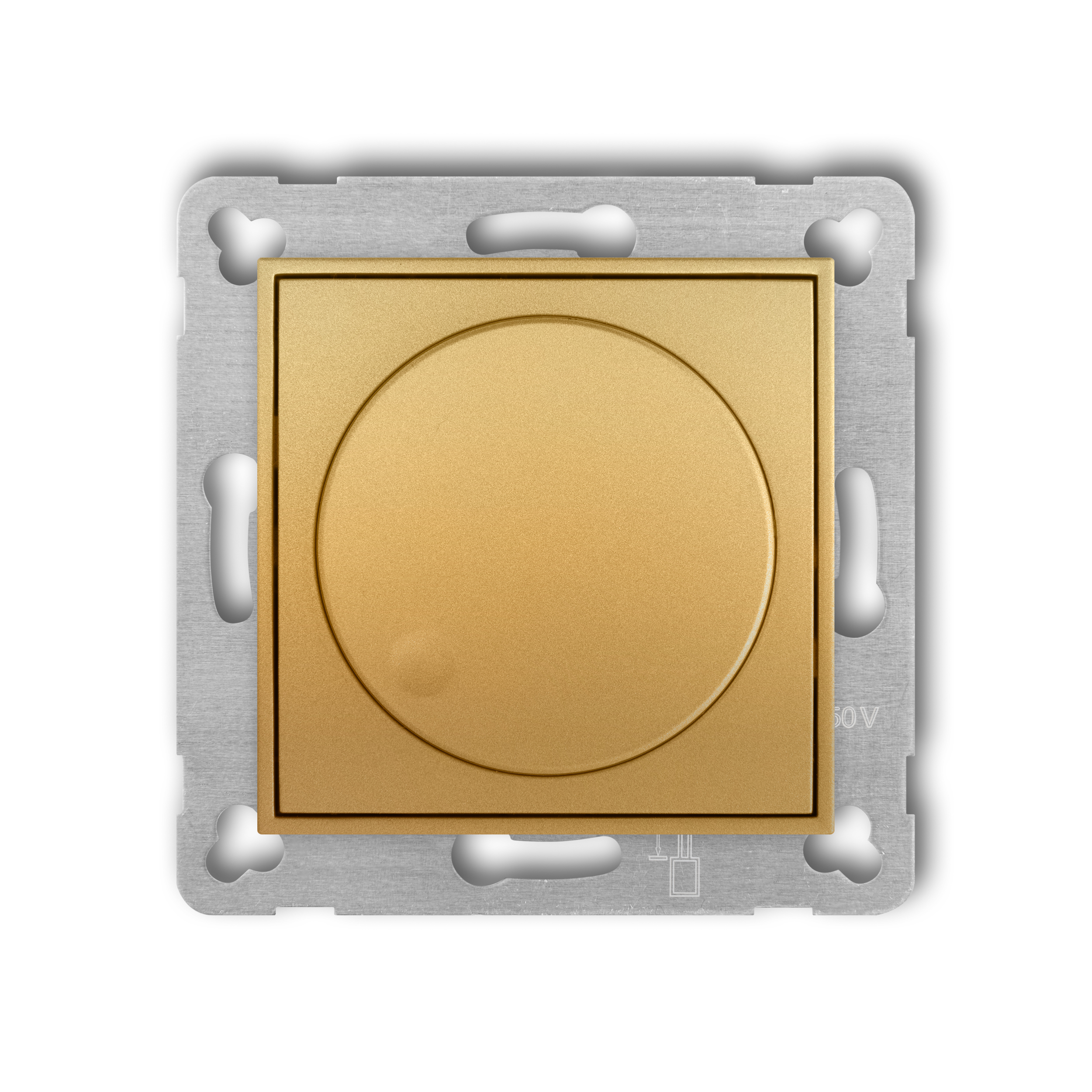
gold
29IRO-3
-
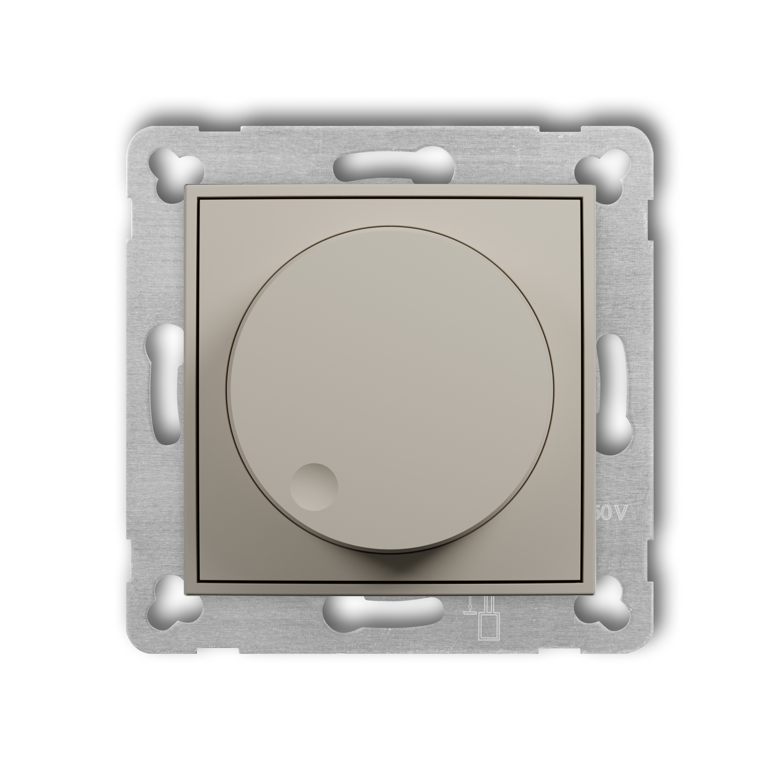
taupe
60IRO-3
-
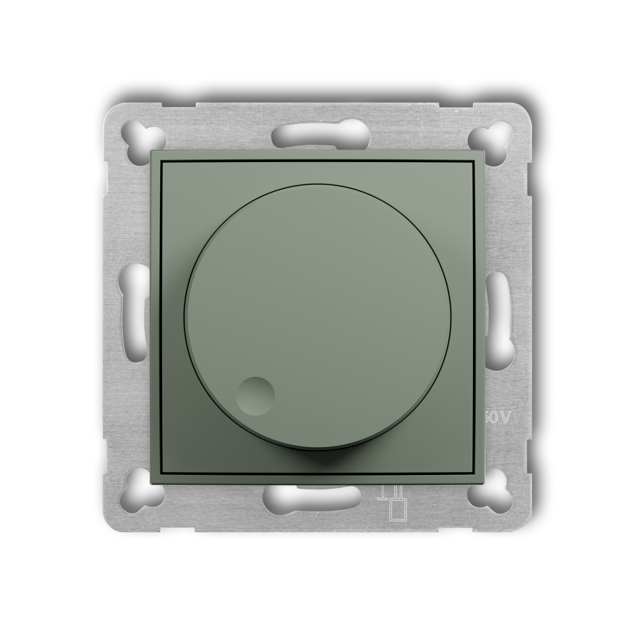
sage
61IRO-3
-
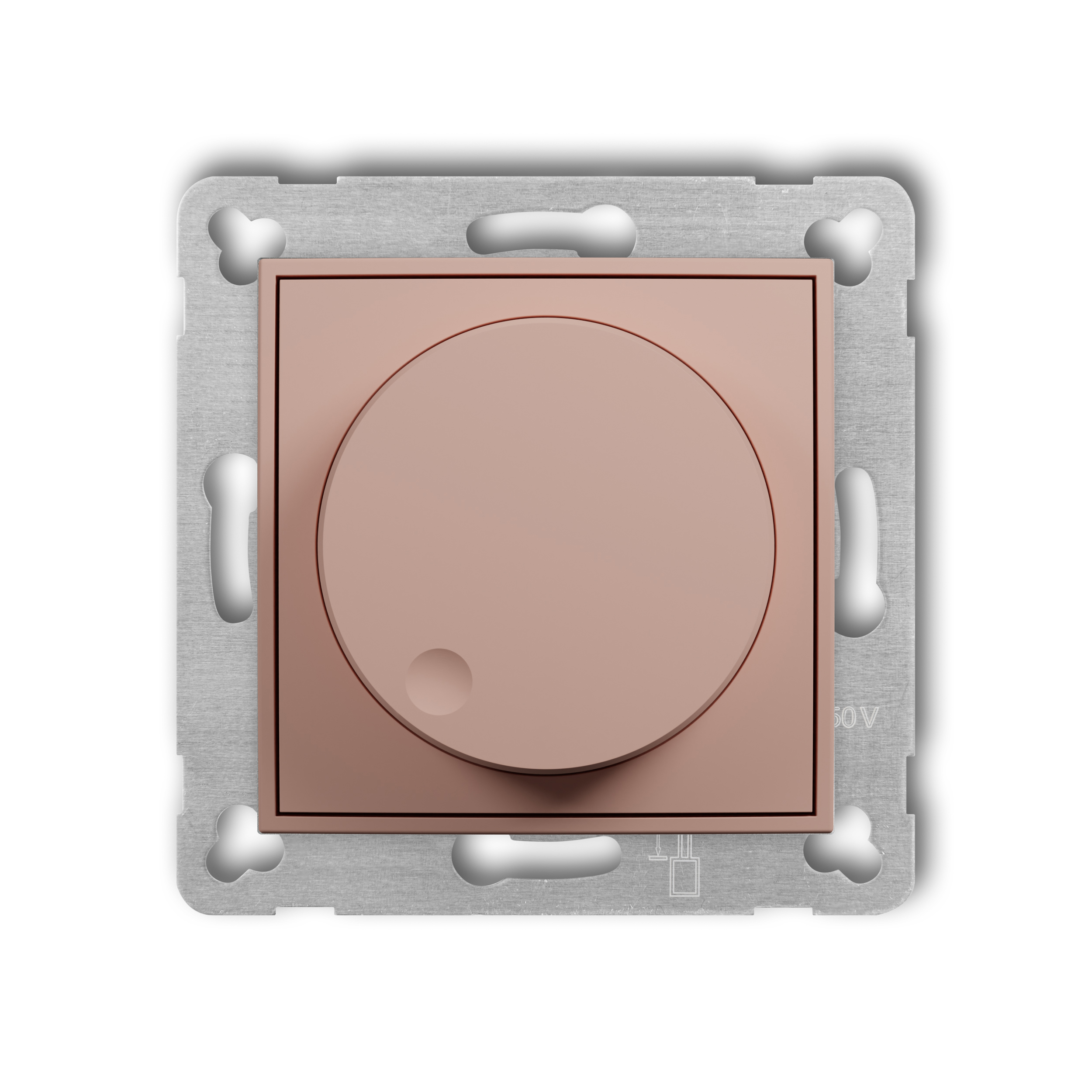
salmon
62IRO-3
-
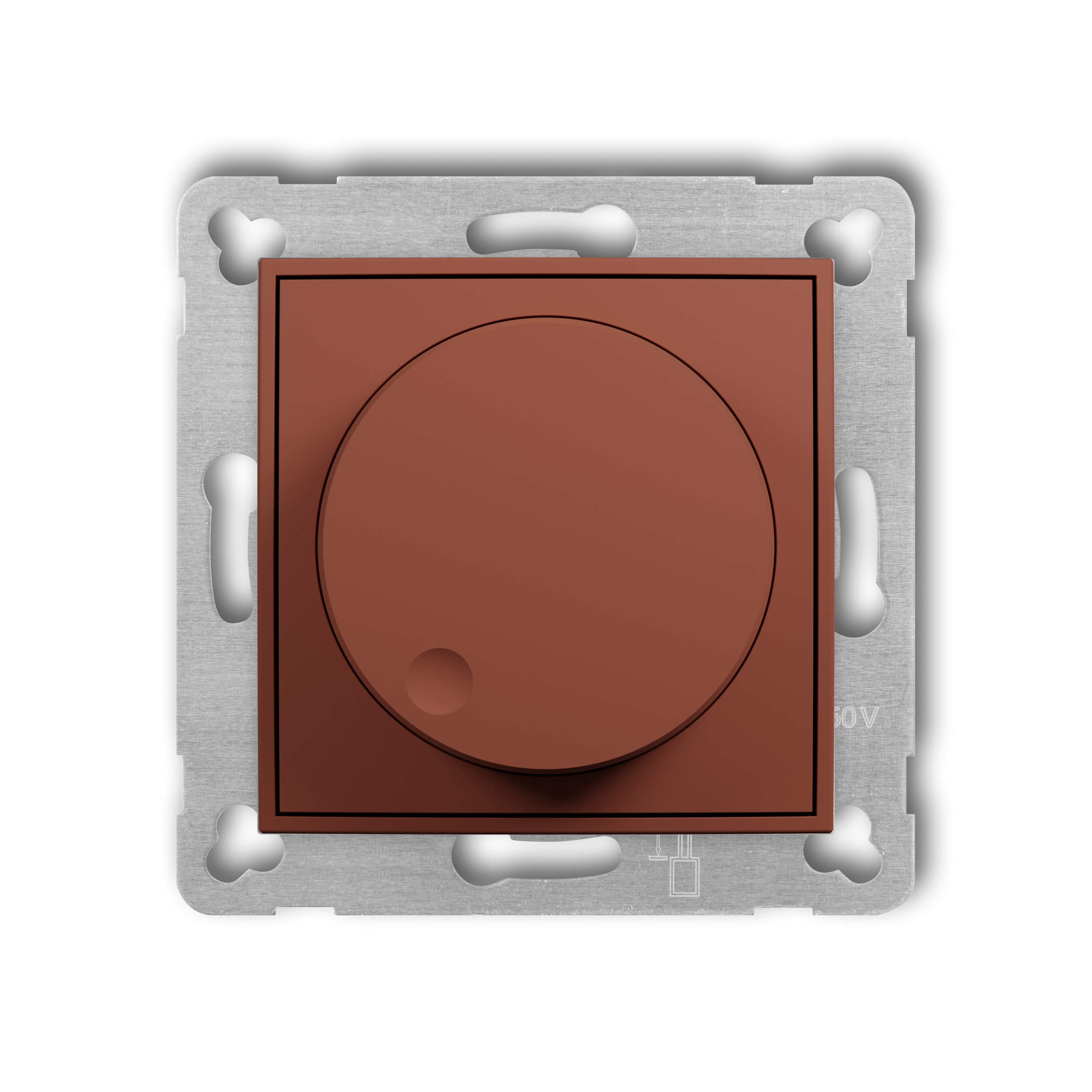
terracotta
63IRO-3
-
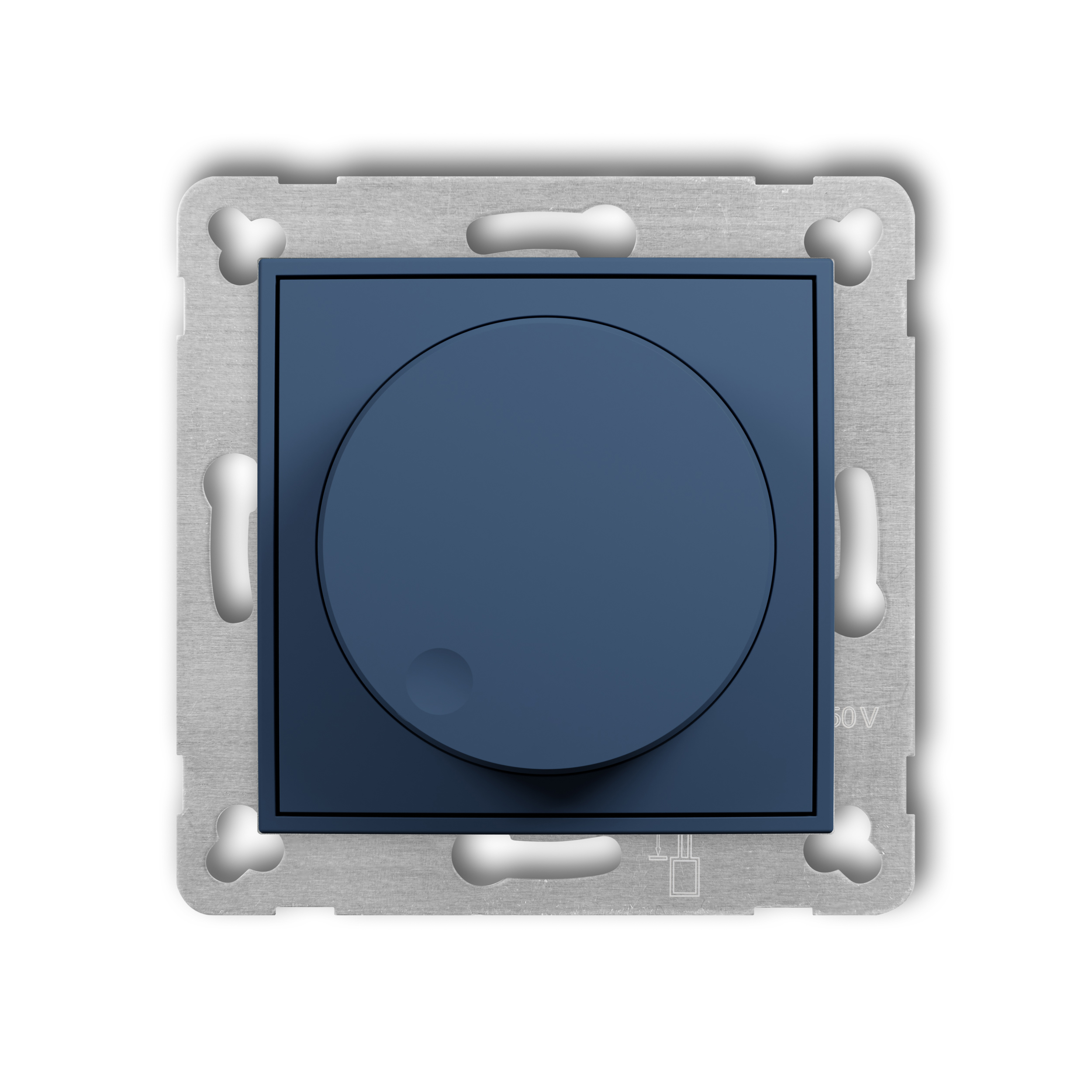
navy blue
64IRO-3
Product description
Downloads
ICON mechanisms and frames are sold separately.
More information in the DOWNLOADS section.
The actual appearance of product may be different from the presented photographs.
Technical data
| Protection index | IP 20 |
| Power supply | 250 V~ 50 Hz |
| Min. control voltage | 1V DC |
| Max. control voltage | 12V DC |
| Max. control current | 50mA |
| Number of connection clamps | 4 |
| Cross section of connection cables | max 1,5 mm2 |
| Fixing of the casing | standard flash-mounted wall box Ø 60 mm |
| Temperature working range | from -20°C to +45°C |
| Safety class | II |
| Surge voltage category | II |
| Contamination level | 2 |
Product variants
-
Electronic dimmer push-rotary mechanism
white
IRO-1
-
Electronic dimmer push-rotary mechanism
matt black
12IRO-1
-
Electronic dimmer push-rotary mechanism
matt grey
27IRO-1
-
Electronic dimmer push-rotary mechanism
matt graphite
28IRO-1
-

Electronic dimmer push-rotary mechanism
sage
61IRO-1
-
Electronic dimmer push-rotary mechanism
terracotta
63IRO-1
Complementary products
Related products
-
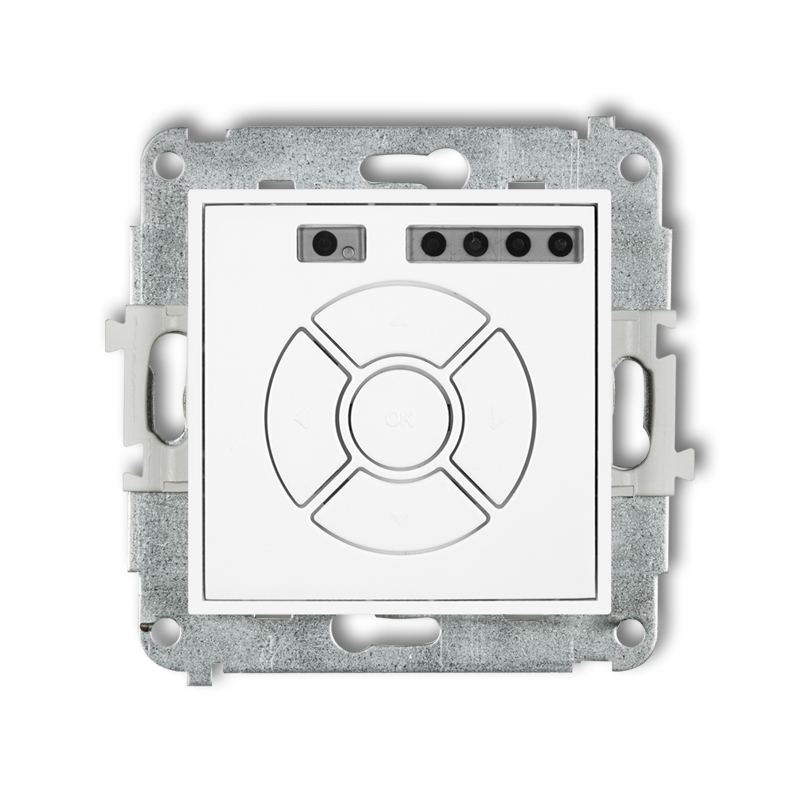
Electronic control roller shutter mechanism (zone button function)
white
ISR-5
-
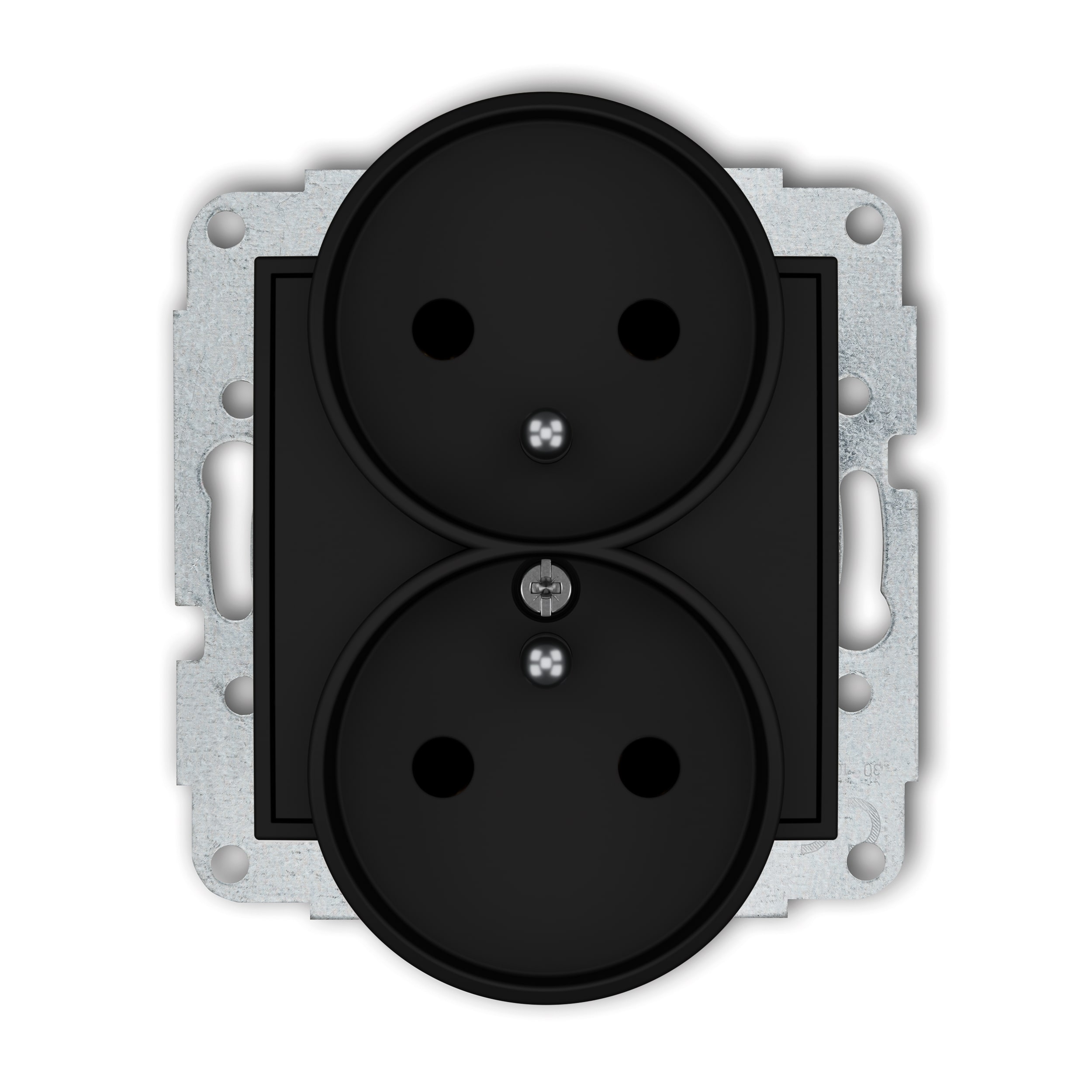
Double socket to a frame with the 2x(2P+Z) earth mechanism (with increased contact protection/shutter)
matt black
12IGPR-2zp
-
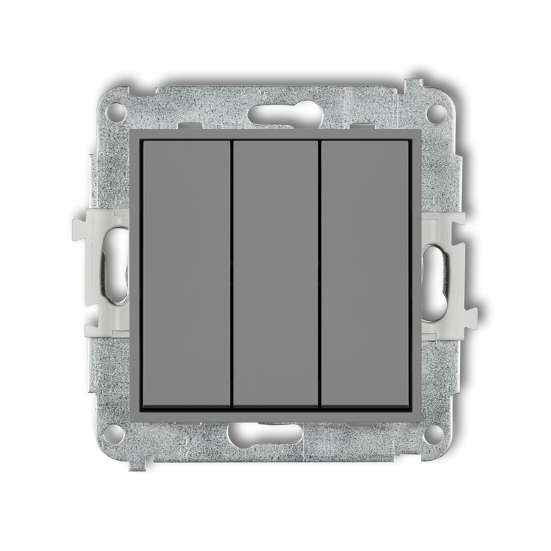
Triple switch mechanism
matt grey
27MWP-7
-
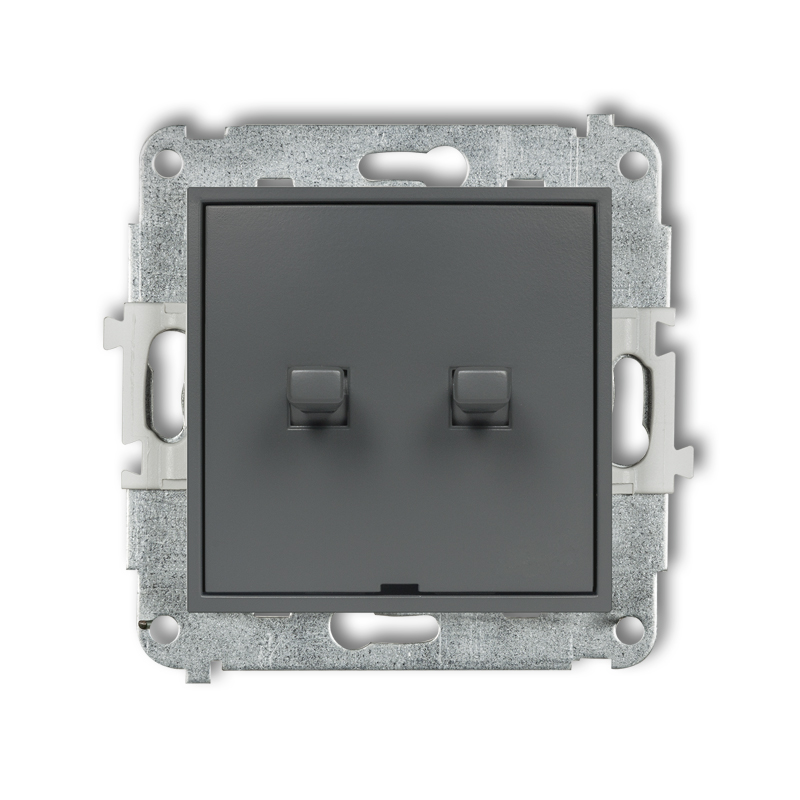
American-style single pole with two-way switch mechanism (double push button without pictograms, separate power supply)
matt graphite
28MWPUS-10.21
-

Electronic motion sensor mechanism
taupe
60ICR-1
-
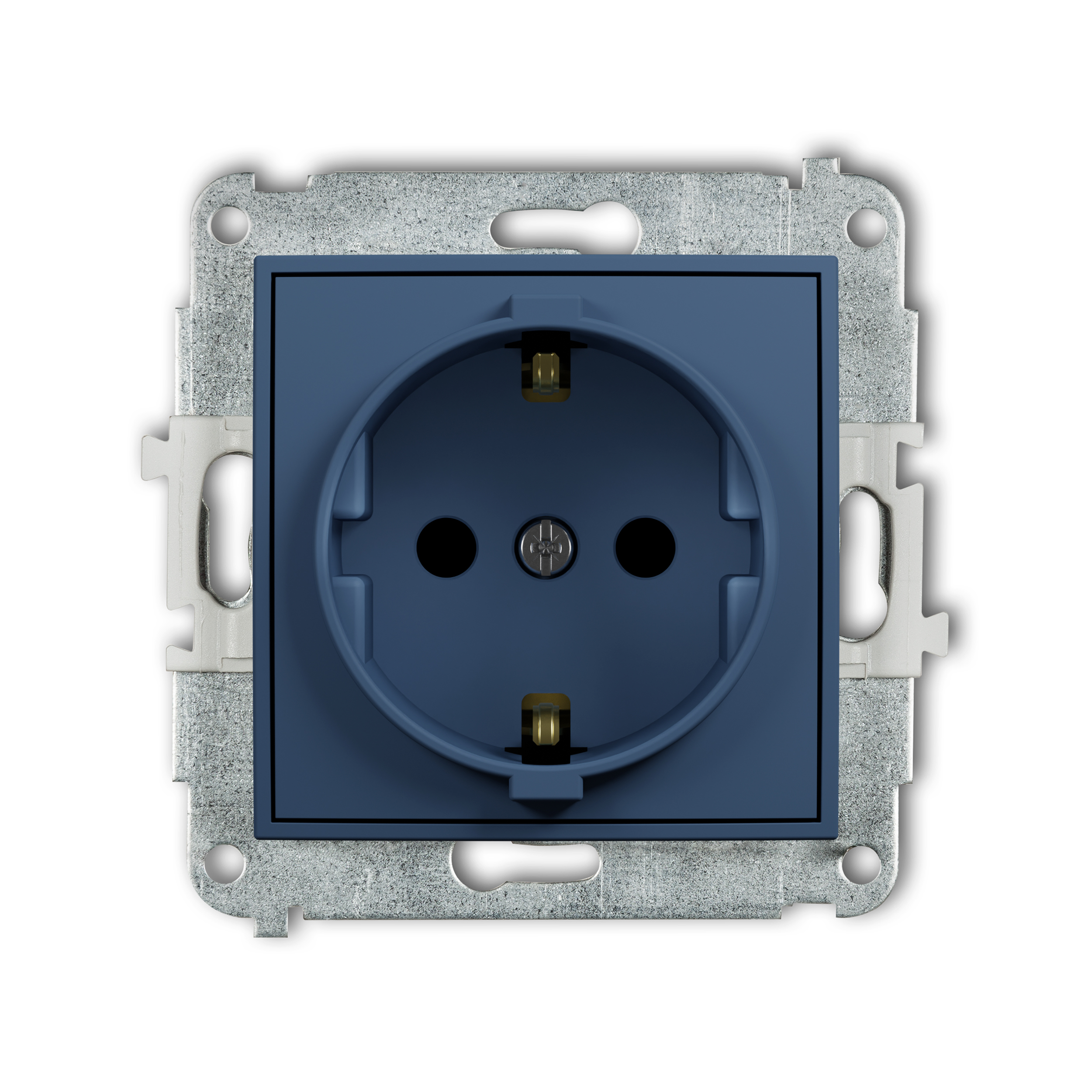
Single socket with the 2P+Z earth SCHUKO mechanism (child protection)
navy blue
64IGP-1sp
3D MODELS
INSTRUCTIONS
-
Assembly manudal of RTV and RTV-SAT outlet sockets _ ICON
-
Assemlby manual computer sockets 5e, 6_ ICON
-
Assemlby manual computer sockets 6a, 7, 8 _ ICON
-
Assembly manudal illuminating module LED for switches _ ICON
-
Assembly manual sealent (IP44) to switches _ ICON
-
User manual hotel switch _ ICON
-
USB charger USB A assembly and connection instruction_ICON
-
USB charger USB A without description field assembly and connection instruction_ICON
-
Doble USB charger 2xUSB A assembly and connection instruction_ICON
-
Doble USB charger 2xUSB A without description field assembly and connection instruction_ICON
-
Doble USB charger 2xUSB C assembly and connection instruction_ICON
-
Doble USB charger 2xUSB C without description field assembly and connection instruction_ICON
-
Doble USB charger USB C + USB A assembly and connection instruction _ICON
-
Doble USB charger USB C + USB A without description field assembly and connection instruction _ICON
-
User manual electronic temperature controller with underfloor sensor _ ICON
-
User manual electronic temperature controller with aerial sensor _ ICON
-
User manual universal electronic week temperature controller _ ICON
-
User manual electronic lighting controller with push and rotary button _ ICON
-
User manual electronic lighting controller with push and rotary button for LED lamps _ ICON
-
User manual electronic lighting controller with push and rotary button 1-10V _ ICON
-
User manual electronic motion detector _ ICON
-
User manual electronic roller blinds _ ICON
-
Doble USB charger 2xUSB C assembly and connection instruction_ICON 30W
-
Doble USB charger 2xUSB C without description field assembly and connection instruction_ICON 30W
-
Doble USB charger USB C + USB A assembly and connection instruction _ICON 30W
-
Doble USB charger USB C + USB A without description field assembly and connection instruction _ICON 30W